Color Code
In this tutorial, we’ll build a color code memory experiment from scratch and interpret it for execution.
This will show how to:
- Implement a code from scratch
- Visualize the code
- Define custom circuits to measure its parity checks
- Create an experiment
- Interpret the result for execution
Overview
In previous tutorials, we learned how to use code factories to create logical experiments. These are very convenient tools, as they provide code implementations out of the box. However, sometimes we may want to create or modify a code that is not included in the available factories.
Loom gives users full flexibility to design their own circuits for syndrome extraction and parallelization. That said, careful attention is required to ensure that the resulting experiments can be successfully interpreted and executed on a backend.
In this tutorial, we’ll explore some of the key details and practical tips needed to construct a custom code from scratch.
Step 1: Create the Code
We’ll begin by building a color code on a triangular patch of a hexagonal lattice.
As usual, the first step is to create a Lattice.
In this case, we define a hexagonal lattice by specifying:
- The qubit positions within the unit cell (
basis_vectors), and - The translation vectors (
lattice_vectors) that repeat the pattern.
The parameters dx and dz determine how many times the cell is repeated along the horizontal and vertical directions.
The size of the patch depends on the code distance, denoted by d.
from loom.eka import Lattice
import numpy as np

# Define unit cell qubit positions
# Qubits 5, 6, 7, 8 are ancillas
sqrt3 = np.sqrt(3)
basis_vectors = [[0, 0],
                 [0.5, -sqrt3/2],
                 [1.5, -sqrt3/2],
                 [2., 0],
                 [1., 0],  # X ancilla
                 [1., 0],  # Z ancilla (same spot)
                 [2.5, -sqrt3/2],  # X ancilla
                 [2.5, -sqrt3/2],  # Z ancilla (same spot)
                ]
# Define unit cell vectors
lattice_vectors = [[3, 0], [0, -sqrt3]]

# Code distance (must be odd)
d = 5

# Lattice length in units
Lx = (d - 1) / 2 * 3
Lz = sqrt3 * Lx / 2

# Lattice length in cells
dx = (d - 1) / 2 + 1
dz = np.round(Lz / sqrt3 + 1)

lattice = Lattice(basis_vectors, lattice_vectors, (dx, dz))
Next, we’ll visualize the lattice.
Before that, let’s define some convenience functions and variables
# cartesian coordinates
coord_dict = {
    (x, y, b): (
        basis_vectors[b][0] + x * lattice_vectors[0][0] + y * lattice_vectors[1][0],
        basis_vectors[b][1] + x * lattice_vectors[0][1] + y * lattice_vectors[1][1],
    )
    for x, y, b in lattice.all_qubits()
}

def inside_patch(q: tuple[int, int, int], eps: float = 0.01) -> bool:
    if q not in lattice.all_qubits(): return False
    x, y = coord_dict[q]
    (x0, y0), (x1, y1) = basis_vectors[0], basis_vectors[1]
    (x2, y2), (x3, y3) = basis_vectors[2], basis_vectors[3]
    m1, m2 = (y1 - y0) / (x1 - x0), (y3 - y2) / (x3 - x2)
    return y <= eps and y >= m1 * x - eps and y >= m2 * (x - Lx) - eps

inside_qubits = [q for q in lattice.all_qubits() if inside_patch(q)]
data_qubits = [q for q in lattice.all_qubits() if q[2]< 4 and inside_patch(q)] # for each cell qubits 4, 5, 6, 7 are ancillas
ancilla_qubits = [q for q in lattice.all_qubits() if q not in data_qubits and inside_patch(q)]
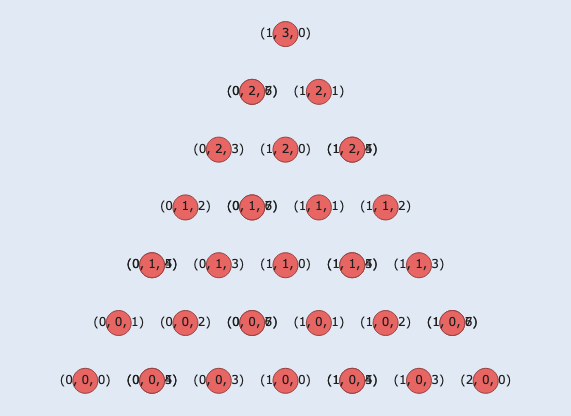
Step 2: Visualize the Lattice
To visualize the lattice, we can use Loom’s visualizer module.
The add_dqubit_traces method allows us to display the qubits, and we can select which ones to show by passing a boolean list.
import loom.visualizer as vis
import plotly.io as pio
pio.renderers.default = "notebook"

# Only show qubits inside the patch
def plot_only(qubit_subset):
    return [True if q in qubit_subset else False for q in lattice.all_qubits()]

show_inside = plot_only(inside_qubits)

plot = vis.StabilizerPlot(lattice)
plot.add_dqubit_traces(show_inside)
plot.show()
Step 3: Define the Stabilizers and Logical Operators
In this example, we’ll choose the lower boundary of the triangular patch for our logical operators.
In a color code, each plaquette corresponds to both a X stabilizer and a Z stabilizer. Therefore, each plaquette has two ancilla qubits, one for each stabilizer type. Here we find what data qubits each ancilla is associated with (its support).
Note that plaquettes near the boundary have fewer neighbors (4 instead of 6).
This doesn’t affect the creation of stabilizers but will be useful to keep track of it when defining the syndrome extraction circuits.
from loom.eka import PauliOperator
from loom.eka import Stabilizer

# qubits involved in the logical operators
lower_boundary_qubits = [q for q in data_qubits if coord_dict[q][1] == 0]

logical_x_operators = (PauliOperator("X" * d, lower_boundary_qubits),)
logical_z_operators = (PauliOperator("Z" * d, lower_boundary_qubits),)

# find data quibit supports for the stabilizers
# if a qubit of the support is missing, replace it with ()
def find_supports(centers: list[tuple[int, int, int]]) -> dict:
    full_supports = {
        (x, y, b): (
            [(x, y, n) for n in range(4)] +
            [(x, y - 1, n) for n in range(2, 0, -1)]
        ) if b < 6 else [
            (x, y, 2),
            (x, y + 1, 3),
            (x + 1, y + 1, 0),
            (x + 1, y, 1),
            (x + 1, y, 0),
            (x, y, 3),
        ]
        for (x, y, b) in centers
    }
    return {c: [q if inside_patch(q) else () for q in s] for (c, s) in full_supports.items()}

supports = find_supports(ancilla_qubits)


# create a dictionary of stabilizers with their gate representations as string as values
# for instance, xx__xx is a stabilizer whose two central support qubits are not in the patch
# ancillas with even number in the cell have X checks and odd numbers get Z checks
stabilizers_dict = {
    Stabilizer(
        (pauli_op := ("X" if ancilla_qubit[2] % 2 == 0 else "Z")) * len(non_empty_support),
        non_empty_support,
        ancilla_qubits=(ancilla_qubit,),
    ): "".join(pauli_op if site else "_" for site in support)
    for ancilla_qubit, support in supports.items()
    if (non_empty_support := [site for site in support if site])
}

stabilizers = list(stabilizers_dict)
Step 4: Create the Syndrome Extraction Circuits
We now want to define our own syndrome extraction routine.
Loom’s Circuit dataclass specifies the sequence of operations applied to a given set of qubits over time.
The main constraint is that no two operations can be performed on the same qubit at the same moment.
When creating a Circuit instance, you must provide a name, a sequence of operations, and the registers on which it acts.
The operations in the sequence can either be subcircuits (other Circuit objects) or gates (circuits whose operation sequence is empty).
Operations are executed sequentially, if you want certain operations to occur simultaneously, you can group them into tuples — each tuple represents one timestep in the circuit’s timeline.[^1]
When constructing a Block, it is therefore important to ensure that all syndrome extraction circuits have the same length, so that they can be parallelized correctly during interpretation.
In this example, we will use a simple extraction routine:
- First, all X stabilizers are measured in parallel,
- Followed by all Z stabilizers.
For each plaquette, syndrome extraction begins with the leftmost qubit and proceeds clockwise. If a plaquette’s support is missing a qubit, we insert a waiting tick (an empty tuple) to maintain synchronization. It is essential to pad the circuits correctly with these empty tuples to represent waiting steps. We must also ensure that the Z stabilizer measurements occur after the X stabilizers — this can be achieved by adding the necessary number of waiting ticks.
In this tutorial, we’ll use the generate_syndrome_circuit() method from RotatedSurfaceCode to create these padded circuits by specifying the positions in the sequence that require padding.
More generally, the Circuit class provides a helper method, construct_padded_circuit_time_sequence(), which can automatically pad circuits by inserting empty tuples after operations that take longer than one tick.
However, this automatic padding may not always produce the most efficient circuit layout.
from loom_rotated_surface_code.code_factory.rotated_surface_code import RotatedSurfaceCode
generate_syndrome_circuit = RotatedSurfaceCode.generate_syndrome_circuit

# Generate a syndrome circuit for each stabilizer type
# All X stabilizers are measured first, followed by all Z stabilizers
# The circuits are padded accordingly for missing qubits in the support

# Get padding indices for stabilizers (pads are represented by "_")
stab_pads = {
    stab_str: tuple(index for index, op in enumerate(stab_str) if op == "_")
    for stab_str in stabilizers_dict.values()
}

# Build syndrome circuits for both X and Z stabilizers
syndrome_circuits = [
    generate_syndrome_circuit(
        pauli_str := stab_str.replace("_", ""),  # Stabilizer Pauli string
        (
            pad_pattern + tuple(range(6, 12))  # For X, add 6 empty steps
            if pauli_str[0] == "X"
            else tuple(range(6)) + tuple(i + 6 for i in pad_pattern)  # For Z, prepend 6 empty steps
        ),
        stab_str,  # Circuit name
    )
    for stab_str, pad_pattern in stab_pads.items()
]
Step 5: Stabilizer-to-Circuit Mapping
Once we’ve built the syndrome extraction circuits, we need to map each stabilizer to its corresponding circuit.
This is necessary because multiple stabilizers can share the same circuit structure.
# Create stabilizer_to_circuit mapping
stabilizer_to_circuit = {
    stab.uuid: circuit.uuid
    for stab, stab_str in stabilizers_dict.items()
    for circuit in syndrome_circuits
    if circuit.name == stab_str.lower()
}
Step 6: Build the Block
We now have all the components needed to build a Block.
In particular, syndrome_circuits and stabilizer_to_circuit are not necessary for the definition of a Block instance but the constraints above need to be met in order for the Eka object to be interpreted properly.
from loom.eka import Block

color_code = Block(
    unique_label="q1",
    stabilizers=stabilizers,
    syndrome_circuits=syndrome_circuits,
    stabilizer_to_circuit=stabilizer_to_circuit,
    logical_x_operators=logical_x_operators,
    logical_z_operators=logical_z_operators,
)
Step 7: Create a Logical Circuit
Next, we’ll define the logical circuit that performs our memory experiment.
We’ll specify the sequence of operations and construct the corresponding Eka object.
from loom.eka import Eka
from loom.eka.operations import (
    MeasureBlockSyndromes,
    MeasureLogicalZ,
    ResetAllDataQubits,
)
from loom.interpreter import interpret_eka

# Define the sequence of operations
operations = [
    [ResetAllDataQubits("q1", state="0")],
    [MeasureBlockSyndromes("q1", n_cycles=1)],
    [MeasureLogicalZ("q1")],
]

color_code_eka = Eka(
    lattice=lattice,
    blocks=[
        color_code
    ],
    operations=operations,
)
Step 8: Interpret the Circuit
Finally, we can interpret the circuit for execution.
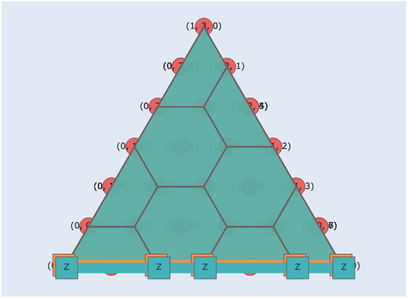
Visualize the Result
We can now visualize the resulting color code, including its stabilizers and logical operators.
stab_plot = vis.StabilizerPlot(
    lattice,
    title=f"Color code d={d}",
)
stab_plot.add_dqubit_traces(show_inside)
stab_plot.plot_blocks([color_code])
stab_plot.show()
Summary
In this tutorial, we learned how to:
- Build a color code from scratch on a hexagonal lattice
- Define stabilizers and logical operators manually
- Create and map syndrome extraction circuits
- Assemble the full
Blockand construct anEkaobject - Interpret the circuit for execution
- Visualize the final structure